
Home : Workshop :
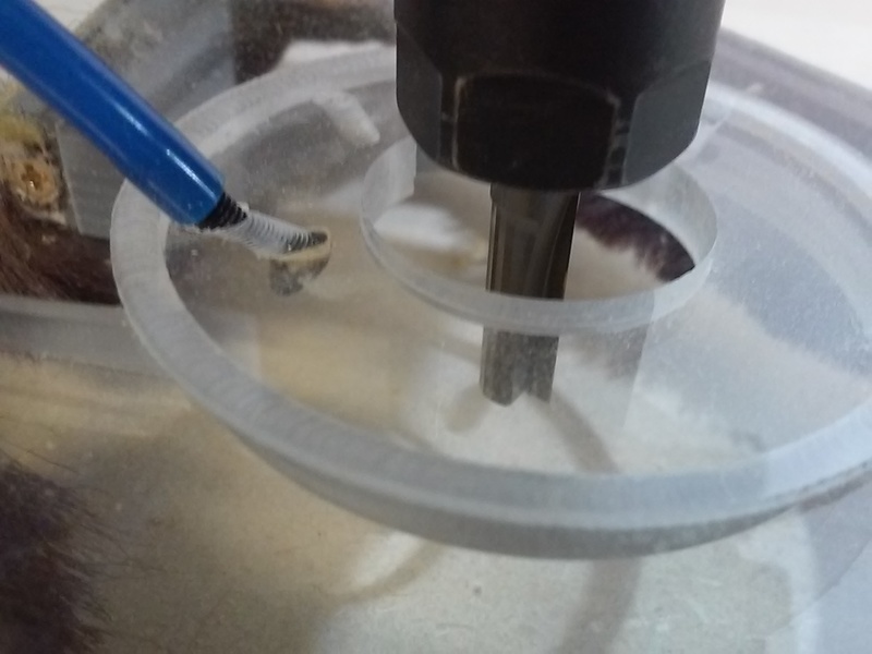
 A Tool Change Probe Plate, e.g. an Estlcam Tool Length Sensor, is used to automatically adjust the Z-axis zero point after a tool change. Pretty much anything (with a wire attached) can be used, but a solidly mounted plate at a fixed location is the most accurate. Since an offset origin helps when processing multiple workpieces, I decided on a combination circle center origin and tool change plate. The plate screws into the closest available spoilboard insert and has three 4mm holes that are compatible with three point center finding and allow the banana plug cord to be out of the way. The plate was machined on my mini mill and lathe from 1" round bar stock.
[ comment | link | top ]
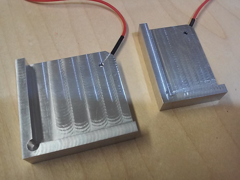
 Also known as a 3-axis touch plate, zero corner finder, edge finder, etc. The primary usage is to automatically probe and set the project origin (X,Y,Z zero) to the corner of the material. I'm not sure why many plates are so big/tall, but low profile plates are easy to hold in place while probing. Because I wanted to be able to use the upsidedown plates for bit change Z zeroing, the wire goes in a stepped edge hole and the tinned end is clamped in place with a flat face setscrew. The plates were made on my mini-mill from 2 x 1/2" bar stock, the 1-1/2" wide one was machined down to 3/8".
[ comment | link | top ]
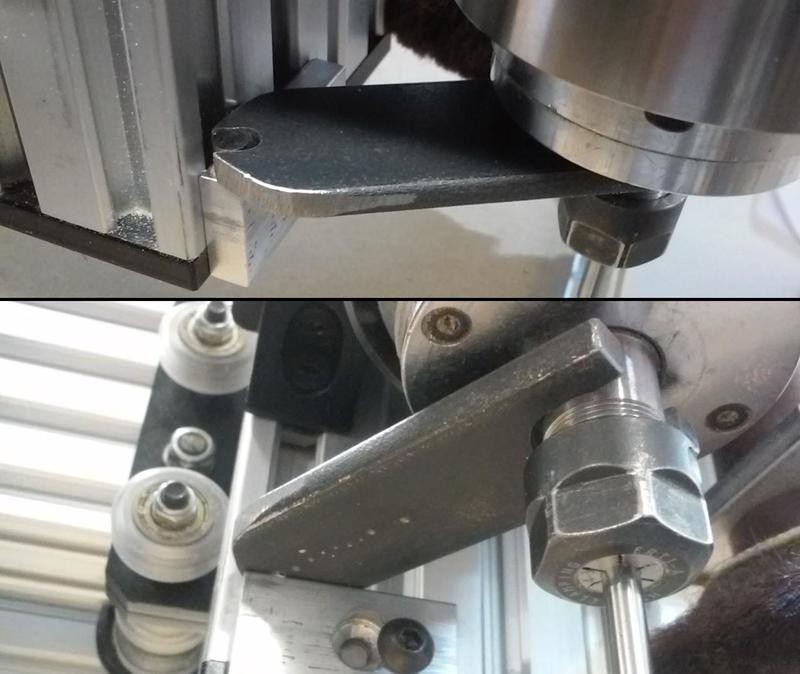
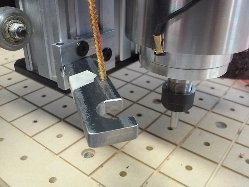
 An OpenBuilds compatible wrench that frees a hand to make tool changing much faster/easier. The design allows the bottom of the collet nut to be a tad below the extrusion end cap, a 1/2" (3/4" pictured) tall dowel plate allows it to be 1/4" lower. The wrench was machined on my mini-mill using 1 x 3/16" hot rolled steel bar stock.
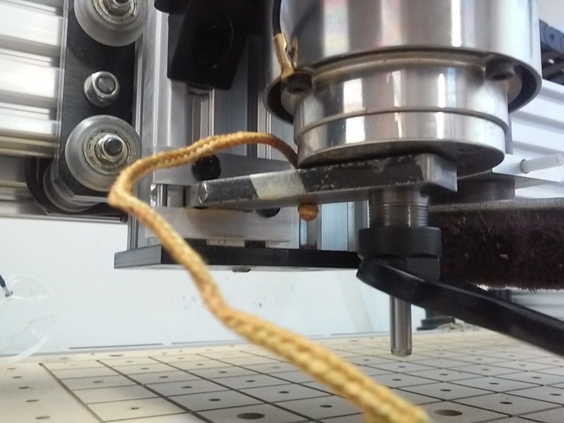
 ...I am currently using a swing arm spindle wrench with the string connected collet wrench hanging on the Z carriage (image). The spindle wrench has to be swung to the side in order to hang the collet wrench.
[ comment | link | top ]
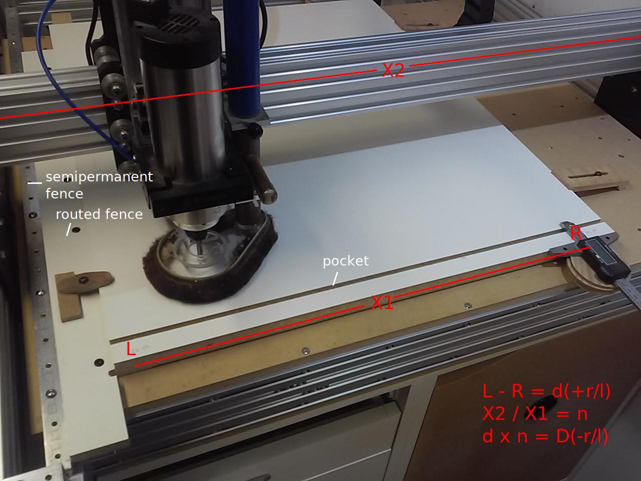
 This topic covers squaring a CNC X-axis to Y-axis using slightly modified versions of the two and five cut methods commonly used to accurately square fences to sawblades. It also covers setting, checking and maintaining squareness using faceted stop screws.
While the article is pretty wordy (which makes the method seem complicated), it's a by the numbers approach that does not rely on any eyeball alignments or measurements. It is a relatively simple method to get and maintain 90 +/- .01 degree accuracy (+/- .1mm over 1m). In theory, the maximum possible accuracy is better than a full step, e.g. < .04mm over 1m (8mm pitch/200).... more
[ page | top ]
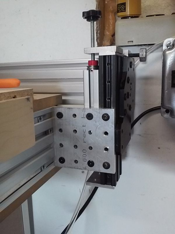
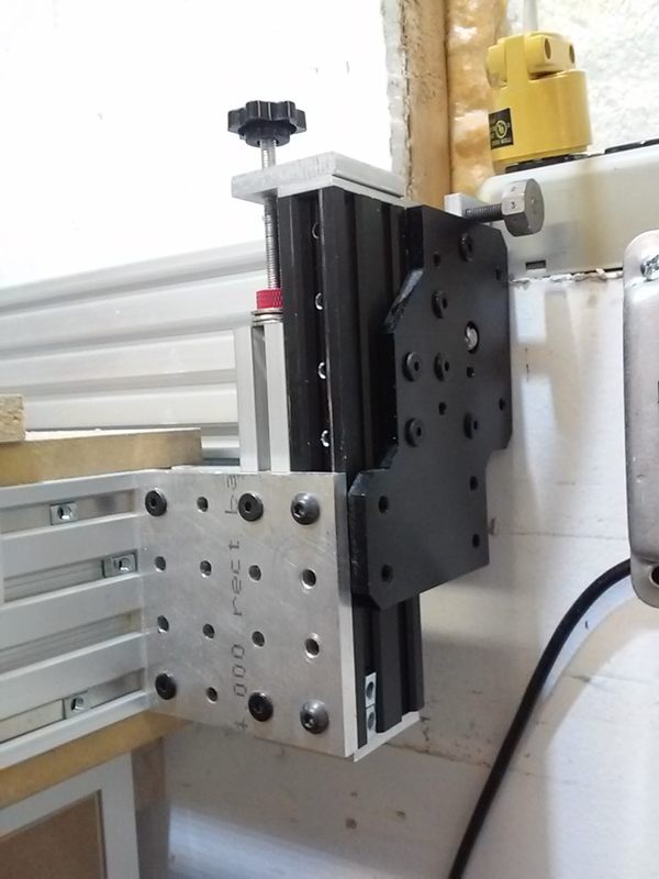
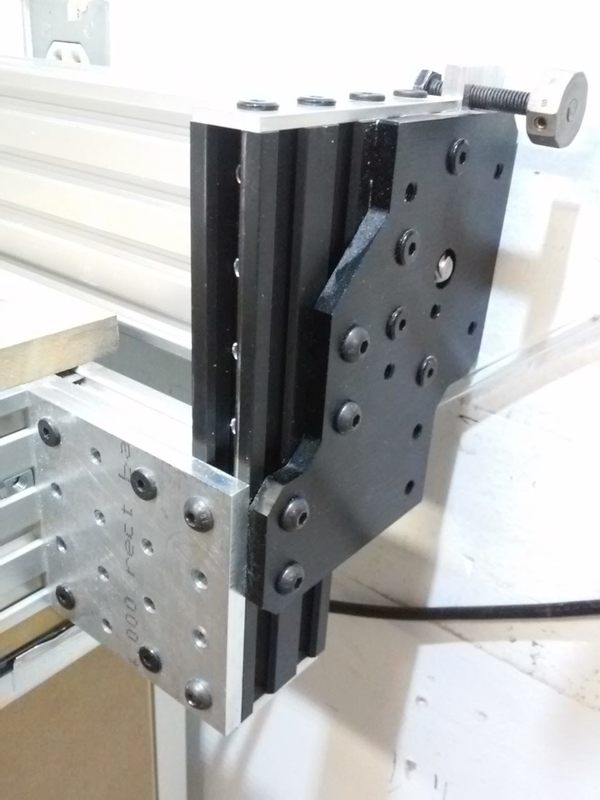
 While being able to machine vertically mounted workpieces gets some attention, there are surprisingly few machines with this capacity built in. As a woodworker/cabinetmaker this was a must have feature. In brief (from a Facebook post), I ended up redesigning some aspects of the WorkBee to accommodate vertical parts. Image includes a vacuum fixture for cutting small dovetails. The front rail of the spoilboard framing is set back 80mm. To get decent Z clearance with vertical 2080 spoilboard framing I moved the framing down 20mm. 2040 extrusion ties the spoilboard framing to the C-rails/end plates (see Workbee 1010 topic), custom plates for the setback.
[ comment | link | top ]
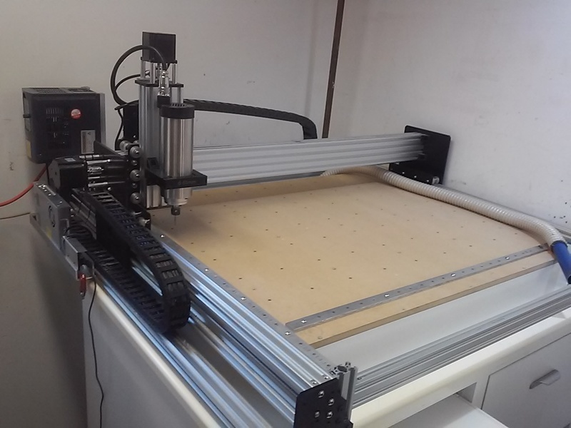
 After using the local Makerspace X-Carve for over a year I decided to buy my own CNC. I settled on a 1010 Workbee kit that included a 1.5kw air cooled spindle/frequency converter. The Workbee is a noticeable step up from the X-Carve, stiffer (... still too much X-axis flex) and more powerful (when using tb6600 etc. drivers). While most of what I will cover applies to any WorkBee, a few things will be specific to the Bulk-Man 3D kits. The mechanical aspect of the kit would have been relatively easy to build had I not redesigned it in the process.
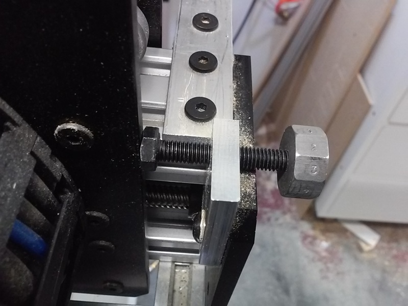
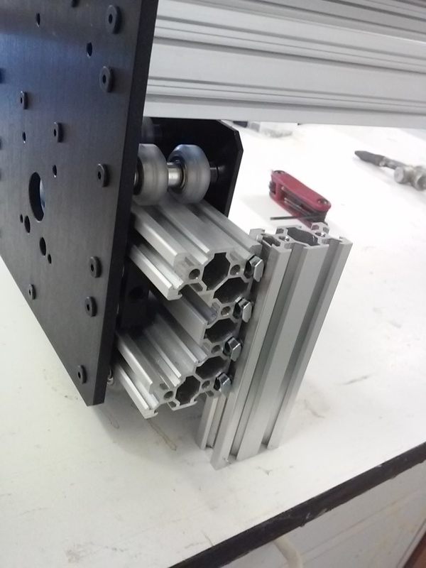
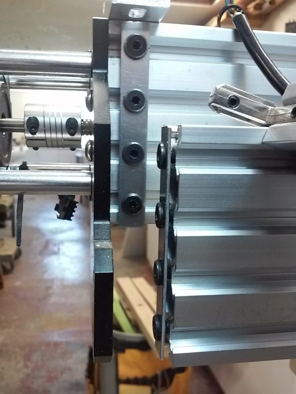
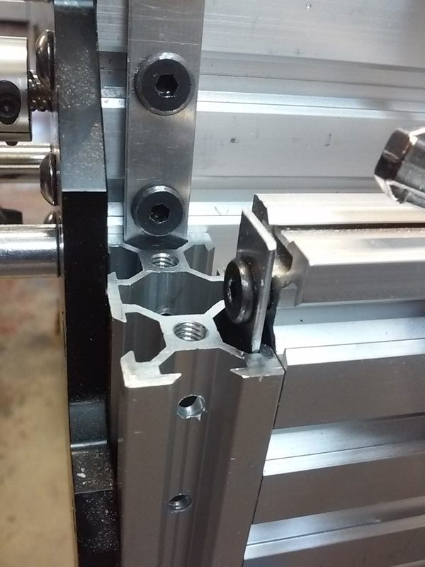
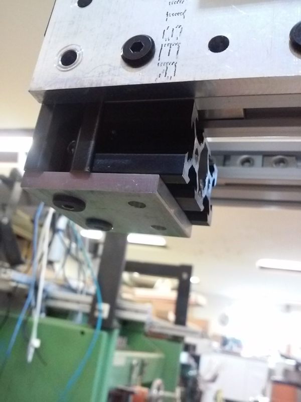
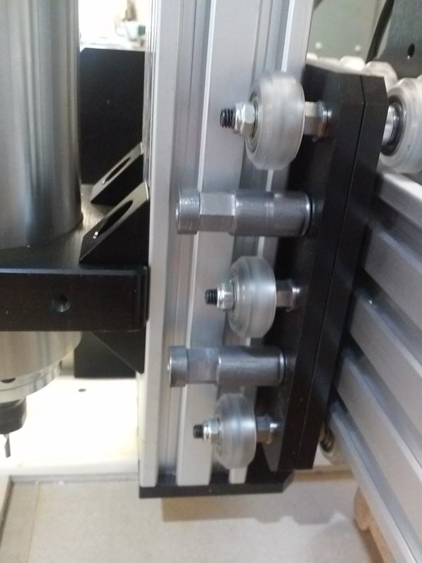
 One thing I didn't like about the design was the spoilboard framing. I decided to mount the 2080 spoilboard mounting rails vertical and parallel to the C-beams. They are mounted to the C-beams and C-beam end plates via vertical pieces of 2040 extrusion. The 2040 pieces have hex key access holes drilled every 20mm which allows mounting them to the C-beam and spoilboard rails. Strips of aluminum fit in the widest part of the T-slot and have 5mm holes 20mm apart to index the screws, align the pieces, and strengthen the joint (plain strips space the spoilboard mounting T-nuts). Four more screws/t-nuts mount the 2040 upright to the end plate. While not very practical, it is possible to move the spoilboard frame up/down in 20mm increments.
 ...50mm knobs, thrust bearings and some odds and ends made it easy to lower my spoilboard another 20mm. Replacing the temporary top plate (since removed) with a permanent L shaped one would almost make up/down adjustment a practical option. The black 2040 'legs' are exactly 160mm long and have end caps to act as accurate stops and insure the Y rails are parallel to the spoilboard. Scrap 2040 spacers can be used to accurately raise the spoilboard 20 or 40mm.
[ comment | link | top ]
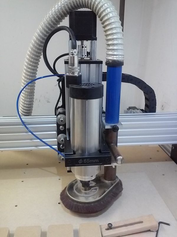
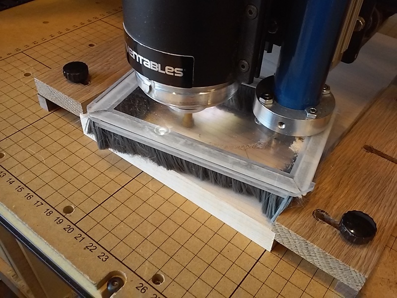
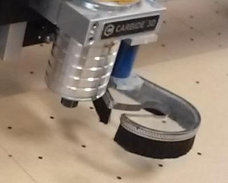
 I don't remember where I got the idea, but I prefer pivoting dust shoes that mount to the X carriage. Shoes mounted to the carriage have a fixed height so the brush is always in contact with the work surface and there is no need to compensate for z-axis/spindle movement. A slot in the shoe makes it easy to swing the shoe out of the way for bit changes.
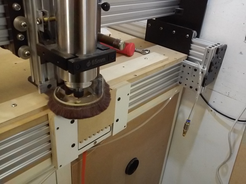
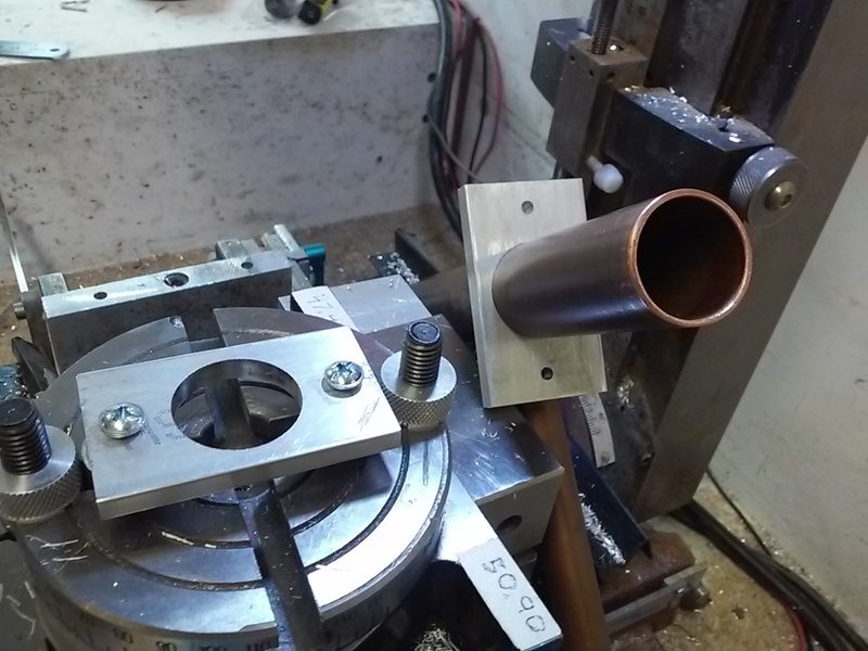
I had already modified my WorkBee to mount the Z plate to the X carriage using m6 screws. The dust shoe mounts are basically big/long headed m6 screws with the head m5 taped for mounting the shoe U bracket. The U bracket is made from 3 pieces of 1/4 x 1-1/2" aluminum. The holes for the 1" copper pipe were made on a rotary table. The T pipe was a boat part and the stem turned out to be a great way to rotate the shoe for bit changes.
The 1" pipe and 1-1/4" hose are plenty big for dust collection. I added the air nozzle/shoe insert to help prevent chip buildup when deep slot rough cutting. The nozzle is an m3 screw with a 1.1mm (1.5 was too big) hole drilled through it. The screw goes through the taped insert and is screwed into the 4mm PU tubing. The tubing runs through the chain and the plan is to add a solenoid to turn the airflow on and off automatically. With my new, quieter and more powerful, vacuum I may need to enlarge the center hole because the vacuum is sucking in the brush near the pipe. While this shoe is an improvement over the one I did for the X-Carve, I'm still trying to figure out a decent way to mount a stiffer, more traditional brush... The shoe I did for the local Makerspace came close.
The design currently results in a slight loss of X capacity. At least for now, I decided against milling an arc in the spindle mount so that I could move the bracket/pipe closer to the spindle.
[ comment | link | top ]
CNC
 I didn't get involved with CNC routers until late '18/early '19 and started with an X-Carve/Easel at the local Makerspace. I built/started using my Workbee 1010 and Estlcam in 2020. This page has Workbee and general CNC topics. The Estlcam subcategory has Estlcam CAM, motion control and hardware topics. Inkscape (1.2) has some drawing for CNC basics (I use EOL AutoSketch for CAD).
Topics on this page: (newest first)
Tool Change Probe Plate
Corner Probe Plate
Hand Free Tool Changing
Relays
Squaring X-axis to Y-axis
Vertically Mounted Workpieces
Workbee 1010
WorkBee Dust Shoe
One minute tool change video (w/ Tool change probe plate, Hand free tool change wrench and Workbee dust shoe)
![]()
Tool Change Probe Plate
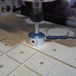
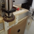
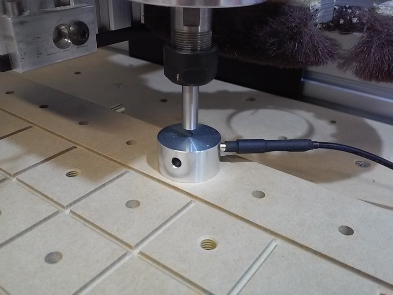 A Tool Change Probe Plate, e.g. an Estlcam Tool Length Sensor, is used to automatically adjust the Z-axis zero point after a tool change. Pretty much anything (with a wire attached) can be used, but a solidly mounted plate at a fixed location is the most accurate. Since an offset origin helps when processing multiple workpieces, I decided on a combination circle center origin and tool change plate. The plate screws into the closest available spoilboard insert and has three 4mm holes that are compatible with three point center finding and allow the banana plug cord to be out of the way. The plate was machined on my mini mill and lathe from 1" round bar stock.
[ comment | link | top ]
Corner Probe Plate
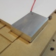
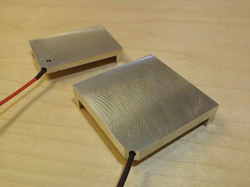
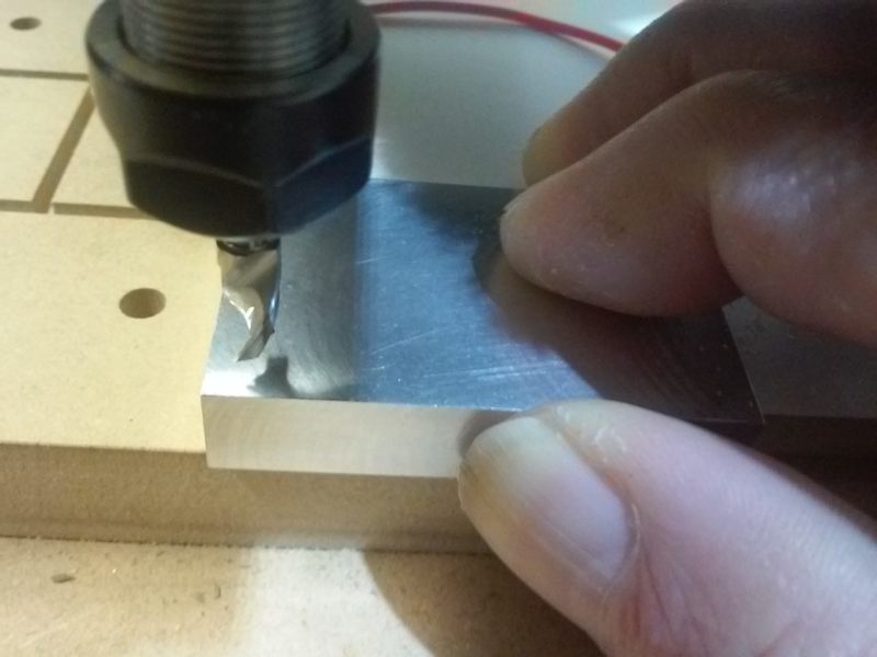
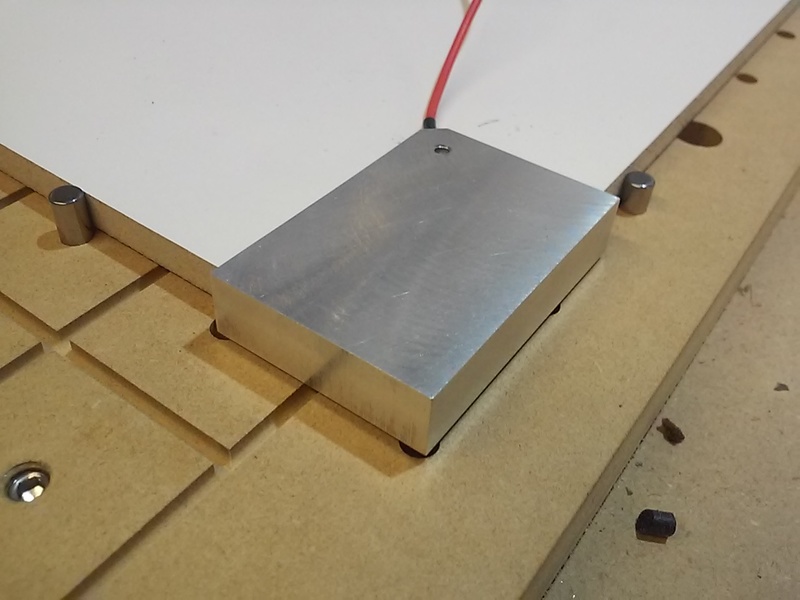 Also known as a 3-axis touch plate, zero corner finder, edge finder, etc. The primary usage is to automatically probe and set the project origin (X,Y,Z zero) to the corner of the material. I'm not sure why many plates are so big/tall, but low profile plates are easy to hold in place while probing. Because I wanted to be able to use the upsidedown plates for bit change Z zeroing, the wire goes in a stepped edge hole and the tinned end is clamped in place with a flat face setscrew. The plates were made on my mini-mill from 2 x 1/2" bar stock, the 1-1/2" wide one was machined down to 3/8".
[ comment | link | top ]
Hand Free Tool Changing
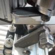
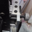
 An OpenBuilds compatible wrench that frees a hand to make tool changing much faster/easier. The design allows the bottom of the collet nut to be a tad below the extrusion end cap, a 1/2" (3/4" pictured) tall dowel plate allows it to be 1/4" lower. The wrench was machined on my mini-mill using 1 x 3/16" hot rolled steel bar stock.
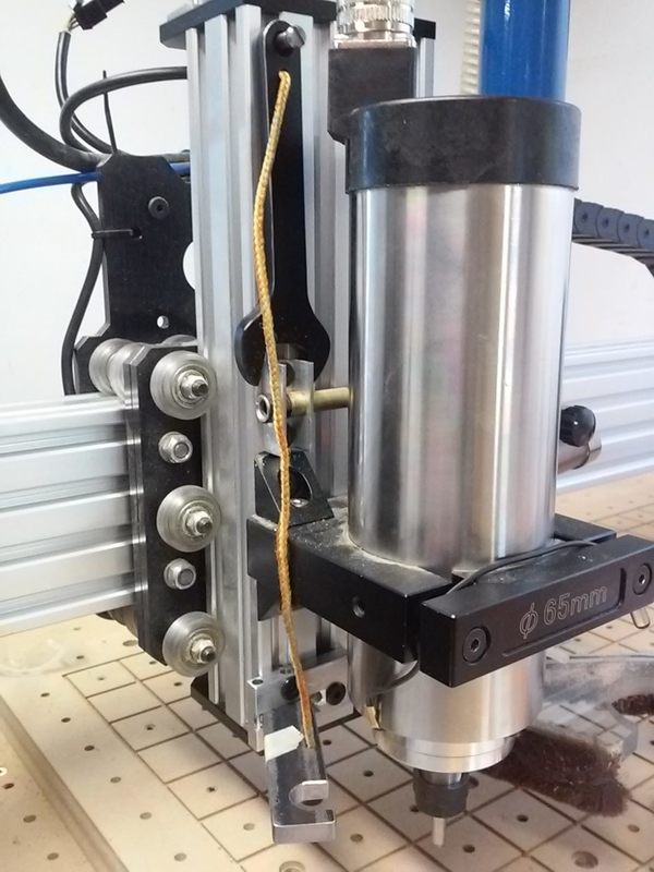 ...I am currently using a swing arm spindle wrench with the string connected collet wrench hanging on the Z carriage (image). The spindle wrench has to be swung to the side in order to hang the collet wrench.
[ comment | link | top ]
Relays
Relays are used to power anything needing more voltage and/or current than the CNC controller can provide. When using an Arduino a relay is needed to power anyhing needing more than 5v and/or anything hooked up to an I/O pin that uses more than 40ma. It is also a good idea to isolate any potentially 'noisy' circuits, e.g. relay coils and limit switches, from from the controller. This topic covers using solid-state, (isolated) electromagnet, optocoupler and transistor relays/switches with CNC controllers. While some of this topic is Arduino specific, most of it applies to any CNC controller... more
[ page | top ]
[ page | top ]
Squaring X-axis to Y-axis
 This topic covers squaring a CNC X-axis to Y-axis using slightly modified versions of the two and five cut methods commonly used to accurately square fences to sawblades. It also covers setting, checking and maintaining squareness using faceted stop screws.
While the article is pretty wordy (which makes the method seem complicated), it's a by the numbers approach that does not rely on any eyeball alignments or measurements. It is a relatively simple method to get and maintain 90 +/- .01 degree accuracy (+/- .1mm over 1m). In theory, the maximum possible accuracy is better than a full step, e.g. < .04mm over 1m (8mm pitch/200).... more
[ page | top ]
Vertically Mounted Workpieces
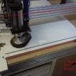
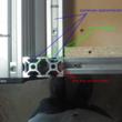
 While being able to machine vertically mounted workpieces gets some attention, there are surprisingly few machines with this capacity built in. As a woodworker/cabinetmaker this was a must have feature. In brief (from a Facebook post), I ended up redesigning some aspects of the WorkBee to accommodate vertical parts. Image includes a vacuum fixture for cutting small dovetails. The front rail of the spoilboard framing is set back 80mm. To get decent Z clearance with vertical 2080 spoilboard framing I moved the framing down 20mm. 2040 extrusion ties the spoilboard framing to the C-rails/end plates (see Workbee 1010 topic), custom plates for the setback.
[ comment | link | top ]
Workbee 1010
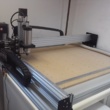
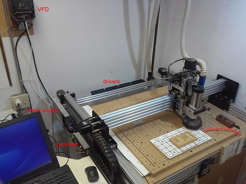
 After using the local Makerspace X-Carve for over a year I decided to buy my own CNC. I settled on a 1010 Workbee kit that included a 1.5kw air cooled spindle/frequency converter. The Workbee is a noticeable step up from the X-Carve, stiffer (... still too much X-axis flex) and more powerful (when using tb6600 etc. drivers). While most of what I will cover applies to any WorkBee, a few things will be specific to the Bulk-Man 3D kits. The mechanical aspect of the kit would have been relatively easy to build had I not redesigned it in the process.
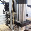
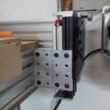
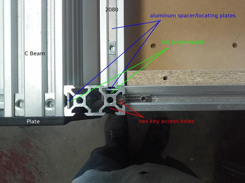 One thing I didn't like about the design was the spoilboard framing. I decided to mount the 2080 spoilboard mounting rails vertical and parallel to the C-beams. They are mounted to the C-beams and C-beam end plates via vertical pieces of 2040 extrusion. The 2040 pieces have hex key access holes drilled every 20mm which allows mounting them to the C-beam and spoilboard rails. Strips of aluminum fit in the widest part of the T-slot and have 5mm holes 20mm apart to index the screws, align the pieces, and strengthen the joint (plain strips space the spoilboard mounting T-nuts). Four more screws/t-nuts mount the 2040 upright to the end plate. While not very practical, it is possible to move the spoilboard frame up/down in 20mm increments.
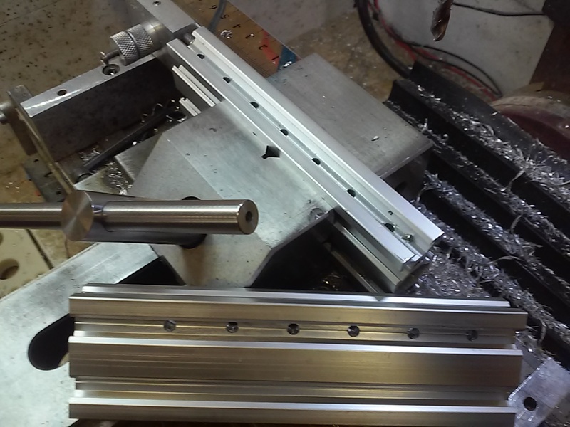
 ...50mm knobs, thrust bearings and some odds and ends made it easy to lower my spoilboard another 20mm. Replacing the temporary top plate (since removed) with a permanent L shaped one would almost make up/down adjustment a practical option. The black 2040 'legs' are exactly 160mm long and have end caps to act as accurate stops and insure the Y rails are parallel to the spoilboard. Scrap 2040 spacers can be used to accurately raise the spoilboard 20 or 40mm.
[ comment | link | top ]
WorkBee Dust Shoe
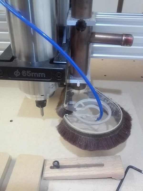
 I don't remember where I got the idea, but I prefer pivoting dust shoes that mount to the X carriage. Shoes mounted to the carriage have a fixed height so the brush is always in contact with the work surface and there is no need to compensate for z-axis/spindle movement. A slot in the shoe makes it easy to swing the shoe out of the way for bit changes.
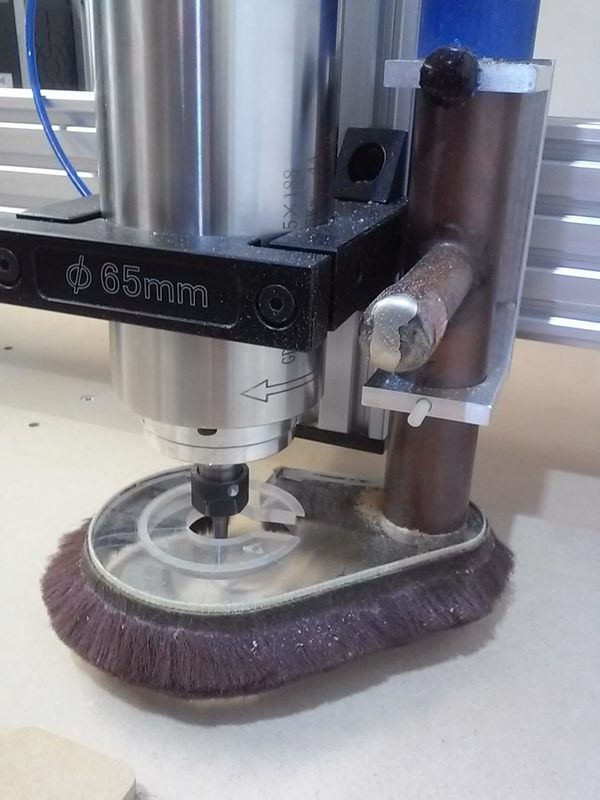
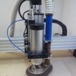
I had already modified my WorkBee to mount the Z plate to the X carriage using m6 screws. The dust shoe mounts are basically big/long headed m6 screws with the head m5 taped for mounting the shoe U bracket. The U bracket is made from 3 pieces of 1/4 x 1-1/2" aluminum. The holes for the 1" copper pipe were made on a rotary table. The T pipe was a boat part and the stem turned out to be a great way to rotate the shoe for bit changes.
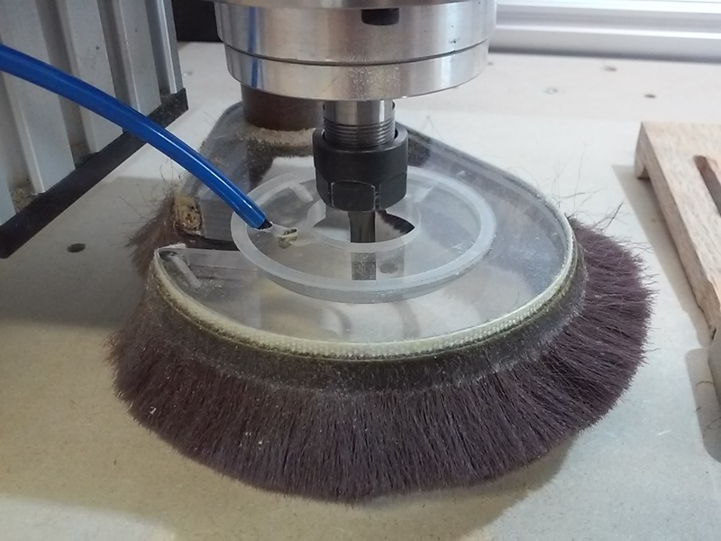
The 1" pipe and 1-1/4" hose are plenty big for dust collection. I added the air nozzle/shoe insert to help prevent chip buildup when deep slot rough cutting. The nozzle is an m3 screw with a 1.1mm (1.5 was too big) hole drilled through it. The screw goes through the taped insert and is screwed into the 4mm PU tubing. The tubing runs through the chain and the plan is to add a solenoid to turn the airflow on and off automatically. With my new, quieter and more powerful, vacuum I may need to enlarge the center hole because the vacuum is sucking in the brush near the pipe. While this shoe is an improvement over the one I did for the X-Carve, I'm still trying to figure out a decent way to mount a stiffer, more traditional brush... The shoe I did for the local Makerspace came close.
The design currently results in a slight loss of X capacity. At least for now, I decided against milling an arc in the spindle mount so that I could move the bracket/pipe closer to the spindle.
[ comment | link | top ]